| |
Sunday 8th July 2001
In an idle moment I decided to casually go over the Robot Wars
rules again, but later on wished I hadn't. (Well actually I guess it was just
as well in the end, but what I found was a bit depressing.) I was reading the
section on radio control gear and spotted a reference to the frequencies used,
which were 40Mhz. This raised alarm bells because I thought the radio
gear I had been donated was 35Mhz. With a quick inspection of my
controller the situation was confirmed. It was the wrong frequency!
I fired a query into Derek Foxwell at Robot Wars asking if there was a quick
solution to upgrade my radio gear to 40Mhz. He responded quickly by saying
"No", and referred me to the forum pages of the RW site where this subject had
been raised before. After a bit of surfing I located an
incredibly
useful site with loads of quite technical info about different areas of
robot building. It covered weapons, radio gear, motor controllers, embedded
micro-controllers, to mention just a few of the topics. It was run by
Paul
Hills, and was very technical is some areas, so be prepared if you visit
it. In the area of radio gears, it gave reasons why it was very difficult to
upgrade a 35Mhz system to a 40Mhz system. That was a bit disappointing because
it meant that I would have to source another radio kit. However, the site had a
lot of other useful links that talked about reducing radio interference, and
how to ensure you installed your system to get the best results. Despite this
whole exercise being a bit of a "downer", I can still continue to use the radio
gear I have in the short term to check the robot operations. It just means for
the moment I won't be able to enter any events!
|
 top top |
| |
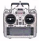
I received a 40Mhz transmitter and receiver from those nice chaps
at Sussex Model
Centre. They were willing to send me only the transmitter and receiver
without the servos, so I saved a bit of money from the normal kit
price.
 |
 |
| I discovered that the 40Mhz systems are allocated
to land-based models, and the 35Mhz band for air-based models. Apart from that,
there was no real technical reason why my old system wouldn't work equally as
well as the new one. |
 |
The next thing I had to do was take
the receiver apart and locate the point in the circuit were I could extract the
serial data stream for the micro controller to decode. After a bit of poking
about with the oscilloscope probe, guess were the connection point was that I
needed to get to. |
| That's right, on the chip with the big blue capacitor glued
to the top of it! |
 |
 |
Realising that I was about to completely invalidate the
warrantee, and also risk permanently damaging the circuit, I gingerly cut away
at the glue until the capacitor was loose, and then I gently de-soldered and
removed it. This modern day surface mount technology is all very well, but it
does mean the chip contacts are very small and soldering a wire onto them is
particularly difficult. I wound a bit of copper wire around the soldering iron
and used this as a very small soldering iron bit so that I could get onto the
board without damaging any adjacent tracks. |
| Once I had soldered the wires on, I managed to put the
capacitor back and then held it in position with instant silicon gasket. |
 |
 |
The receiver looked like this after the job was complete, and
what's more, it all seemed to work! The next thing I needed to do was modify
the micro-controller software a bit because the channels allocated on this
transmitter were different to those of the Pulse Core system. This should be a
simple job of changing the value of a couple of variables, and downloading a
new version to the controller. (I hope!) |
|
top |
| |
| I decided to try and hide all the delicate, low powered motor
control circuit in a single box, (a) to provide some shielding , and (b) to
make it easier to fit into the robot. I got the receiver, the gyro, the
micro-controller, and interface board in there. The Receiver and
micro-controller batteries will have to be mounted outside the box, likewise
the power MOSFETs on their heat sink "bricks." |
 |
|
top |
| |
I made a few small changes to the motor control software to match
the new radio gear characteristics. There was a small offset in the joysticks
range that meant that the mid position was off centre, and the maximum range
couldn't always be achieved. After a few changes, the joystick operations were
back in range with the trimmers set to mid position.
|
top |
| |
I managed to squeeze a bit of time in a very busy weekend to make
the fourth axle mounting bracket. The welding was still not perfect, but
improving. On a couple of seams I don't know what I did, but the weld just
flowed freely and easily and it was difficult not to end up with a nice looking
weld. On on a couple of others it wasn't until I had chipped off the slag that
I realised the weld had only taken to one side, and I needed to go over the
weld again. I would like to know what it is that I do each time that makes all
this difference!
|
top |
| |
| I collected the motors shafts and bearing spacers from Bill
at Settform. The spacers now allowed the bearings to hold the shaft in the
right place for it to mesh with the stub end of the motor. The studding used to
mount the bearings on will also come in handy to help mount the motors onto the
chassis of the robot. |
 |
 |
top |
| |
|
|