July 2004
Thursday 8th July 2004
I've been thinking a bit more about how I can implement a current limiting feature using the auto-protected MOSFETs I've discovered. I've been caught out before with what seemed like good devices by not checking the data sheets properly, so this time I decided to check the details of my existing MOSFETs against the auto-protected ones.
It didn't take long to establish that the "ON delay" and "ON rise times" of the auto-protected MOSFETs were about three times as long as my existing ones. If I were to replace my existing MOSFETs with the new ones, I was potentially going to get myself into a lot of trouble with switch on and off times. I had also been looking at some of the forum discussions from people who had used the auto-protected MOSFETs, and many were using these devices in series with the power leads rather than within the H bridge driver circuitry. Some people were concerned about the fact that the current through the devices was achieved by it working in its "linear" region. What this means is that the device's "on" resistance increases from its normal value of about 0.02 ohms, to something like 0.5 ohms. The difference doesn't seem a lot until you work out the power the device is likely to dissipate.
When working within its normal range and carrying, say, 48 amps from a 24 volt supply, the power dissipated is
I2 x R = 48 x 48 x 0.02 = 46 watts.
When it enters its current limiting region, and in a worst case scenario, it would dissipate
V x I = 24 x 49 = 1175 watts
which will warm up the device nice and quickly! Luckily the device has thermal shutdown as well, so if it overheats when current limiting, it will simply become open circuit and the current will drop to virtually zero until the device cools back down again. Provided the device is mounted on a big enough heat sink, and the period of time when the device is in current limiting mode is short, you should not enter thermal shutdown, and there should not be a problem.
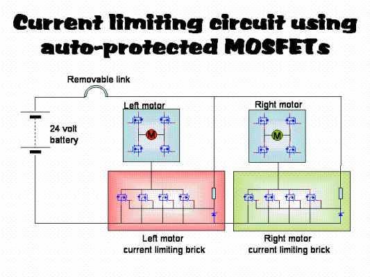
On this assumption I placed an order for a dozen devices from Rapid Electronics so that I can build two current limiting "bricks"; one for each of the drive motor drive supplies as shown in the schematic diagram below. (only the main elecments of the circuit are shown here!) In each "brick" I will parallel four or five together so that they will "current limit" only when they gets to about 200 amps, which should be ample for the Hog.

When the MOSFETs arrive, I will work on making a suitable plate that will act as a heatsink as well as a support bracket for the devices.