November 2000
Thursday 2nd November 2000
|
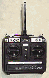
I have been given a 7 channel radio transmitter and a gyro by my brother Philip. There is no receiver with the radio gear but at least I now have half the radio equipment I need to in order to control steering and forward/backwards control from one joystick, and still leave enough channels for some weapons. The gyro is one with variable gain control and seems to work quite well with my existing motor drive circuit. |
 |
|
I have also built one motor driver circuit with a greater current handling capability in preparation for when (and if!) the winch motors finally arrive. Each segment of the full bridge driver circuit now has three MOSFETs in parallel which should be able to handle several hundred amps. I didn't have enough MOSFETs to build two circuits, so will ask Farichild if they would like to donate some more samples. |
 |
Tuesday 8th November 2000
I had confirmation today from Superwinch that I should be receiving two motors in the post shortly. I won't hold my breath but I will keep my fingers crossed.
Saturday 11th November 2000
Went to see my parents today and collected my father's old invalid vehicle. It's an electric tricycle that looks a bit like the old Ariel 3 bikes (if anyone can remember that far back). It hadn't been used in quite some time, but I was hoping there would be some parts I could salvage for the robot.
Monday 13th November 2000
This was my third attempt at modifying the motor drive circuit by including a DC DC converter to fully turn on the MOSFETs. I took a lot of pain to ensure that the converter worked on its own on the bench, then in the circuit with the motors idle before slowly winding up the wick. The converter lasted all of half a second before going bang and wasting another £8.10. Slightly de-motivated I replaced the dead converter with a pack of six AA batteries and tried the circuit again. The MOSFETs were now being driven hard on, and the motor speed was noticeably faster. With the promise that my theory was right, but my execution of the solution flawed, I will give it one more shot before making the AA battery pack a permanent feature. Looking over the RS site I found a different DC DC converter, together with a diagram of what was inside. This one had short circuit protection and thermal shutdown features so if this one doesn't do the job, the batteries will instead. The price was also reasonable at £7 ish.
Some more free Power MOSFETs arrived from Fairchild semiconductors, which means I can build the improved driver circuit for the other motor now.
Wednesday 15th November 2000
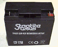
| The two Steatite batteries that I ordered some three months ago arrived today. At last I could replace the trusty old battery charger with a real power source. However, the higher capacity power source combined with the new higher power carrying capacity of the MOSFETs brought about a few unexpected problems. |  |
The new MOSFETs had a slightly lower turn on gate voltage that the previous ones, which meant that when the MOSFETs should have been turned off, they weren't! This wasn't a big problem with the battery charger in place, but with the battery now supplying the power, the supply leads started to get warm and sag. The circuit board also suffered a bit when a couple of tracks acted as fuses and went "pop". On top of this, and to add to the confusion, one of the MOSFETs decided to break down and short all its pins together. With the offending component eventually being identified and replaced, it took a bit of fiddling and scratching of the head before I discovered why everything else was now getting hot and smelly. With only the aid of a voltmeter instead of an oscilloscope, it is not always easy to identify dynamic circuit problems. With a close inspection of the old and new data sheets, I identified potential problem but would put off working out the solution until another day because it was now 1.00am in the morning!
Friday 17th November 2000
Decided to order two high current relays from Display electronics to act as fail-safe devices. They were only £5.50 +VAT, and quite a bit cheaper than comparable ones I had seen elsewhere.
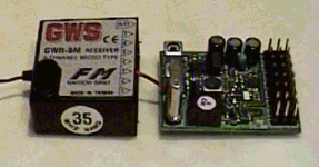
| The new 8 channel receiver arrived from Suffolk model centre. It was made by GWS and was about half the price of an original JR device. I connected it up and it worked fine with the JR transmitter I had been given by my brother Philip. I wanted to get to the heart of the receiver and decode the serial data stream rather than the individual channel ports. In this way I could decode all the transmitter channels with the minimum of micro-controller ports being used. I took the top off the receiver and spotted a chip connected to all the channel output pins. By looking at the on-line data sheets on the RS web site, I identified the chip as a serial to parallel converter. Armed with this knowledge, I think I should now be able to decode the serial bit stream okay. |  |
Sunday 19th November 2000
I tried to pin down why the power the consumption of the motor driver circuit was still high, and why another two MOSFETs had gone pop. After another hour of fiddling and scratching my head with only the trusty voltmeter as a diagnostic aid, I decided to opt for a more lateral thinking solution. I would change the sequence in which I pulsed each of the MOSFETs from within the micro-controller's program to reduce the change of two of them being on at the same time. There were time lags in turn on and turn off times, and I wasn't sure if this was a contributory factor. Removing the opportunity for them to be on at the same time seemed to be a good option given my limited instrumentation resources. If I had an oscilloscope I may have been able to pinpoint the problem more accurately, but unless I am donated one, an oscilloscope is a luxury I can't afford at the moment!
Tuesday 21st November 2000
Communicated with SuperWinch to find out what was happening with the drive motors. They replied saying that there were no motors in the UK, so they would send some over from the USA. I wonder if they will arrive this side of Christmas!
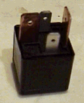
| The two high current rated relays arrived from Display Electronics. I can now start to make up a wiring loom out of larger cables that can carry the power required by the Winch motors (when they finally arrive) and go via these "fail-safe" relays. |  |
Thursday 30th November 2000
Received a couple of emails from people who have looked at my site and had obviously read parts (if not all) of the dairy section. It was quite nice to know someone had got something out of the site and that it wasn't a complete waste of time just building up my ego!