January 2003
Thursday 9th January 2003
Armed with my new motor shafts, I removed the drive sprockets from the old winch motors and bolted them to the new shafts. After that I had to secure a sleeve to the end of the shaft so that it would fit the inside of the bearing that were going to support the free end. To lock the sleeve in place I needed to drill a small hole through the sleeve and shaft, in which I would insert a spring pin. I held the shaft in the hand vice and then used my cheap and "no so cheerful" bench drill to drill the hole. The result was awful as the drill bit jittered around, and made the hole anything but true and straight. That was it, this was the last time I would use that lousy bench drill! In a fit of depression I went off and ordered a more sturdy bench drill from Screwfix.com on-line. Their catalogue had just plopped on my doormat advertising post Christmas sales, so this was an opportunity I couldn't resist.
Monday 13th January 2003
|
Two parcels arrived today; one from Screwfix and the other from SKF bearings. The parcel from Screwfix was my new bench drill which would mean I could junk its "cheap and nasty" predecessor. The new one was purpose build and a lot stronger. i.e. it had a sturdy stand, and its own motor instead of clamping a conventional electric hand drill. When I had assembled it and securely bolted it to the bench top, I gave it a go. What a difference! There was no jittering, and the hole was straight and true. With hindsight, I would recommend that anyone who was considering buying a bench drill does NOT go for one that takes an electric hand held drill. The quality of the resulting holes it too variable. Spend the extra few pounds and get a proper bench drill! |
 |
|
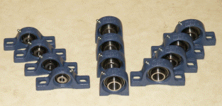
The other package contained 12 bearings that SKF had kindly donated. I had chosen a selection of cast iron Plummer block bearings that I would use to mount the motor drive shafts, and wheel axles on. These cast iron mountings were a lot sturdier that the previous pressed steel ones, but the penalty was they were a lot heavier. That aside, I think they will be easier to mount on the chassis, so "some you win, some you loose". |
 |
Tuesday 14th January 2003
I took a day off work to visit Norgren's factory in Farnham. I had been talking with their quality manager Ben, who had offered me the chance of going through their bins for surplus items. This was an offer I couldn't resist. Even if I only found the odd small fitting, it would be a useful exercise to see the inside of a pneumatics factory.
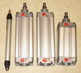
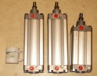
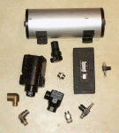
When I arrived we had a chat, and then they pointed me towards a pallet full of boxes that had been returned to Norgren for one reason or another. Ben offered me anything on the pallet because they would be thrown in the bin shortly. It was like Christmas all over again! On the pallet I found three 100mm bore cylinders with different strokes, and a number of other odd fittings. Each one of these cylinders would cost in the order of 180 pounds, so I left the factory very happy.
In the pictures below you can see the relative size of the new rams compared to the old one, and a tea cup!
|
|
|
|
When I arrived home I found another parcel had been delivered form
Norgren. This was from their other factory in Litchfield, where
I had been talking with their sales manager Brady over the past
few months. They too had sent me a few items, so I was now starting
to get a good selection of alternatives for the hog's flipper. I
was still short of quite a few pneumatic parts, but both Brady and
Ben had hinted that they would be willing to supply these too. What
can I say, "THANK YOU NORGREN, you've been tremendous." |
 |
Friday 22nd January 2003
During the past week I have been thinking hard about the chassis design. I wanted to build it on the philosophy of the weapon taking priority over all the other elements, but time was drifting on and I hadn't got all the pneumatics in my grubby hands yet. There were still a few elements I could work on though without compromising the weapon, so I turned my attention to the transmission, and in particular the wheel axle and motor supports. I wanted the motors to be centrally located in the robot so they stood less chance of being hit by opponents as they were with Hog 1. I also wanted to improve access to the wheels so that I could pump them up or chance them a bit more easily.
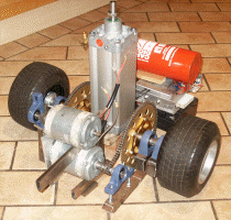
I made a support plate out of 6mm aluminium that bolted to the mounting studs of the motors, holding them one above the other. I was going to take advantage of the fact that the motors had drive shafts protruding out of both ends, and the fact that the motors ran at slightly different speeds in one direction than the other. With both motors oriented the same way and putting the drive sprockets on opposite ends, it would reduce the speed mismatch between the left and right drives. Having the motors one on top of the other fixed the distance between the left and right wheel sprockets, and ultimately determined the space I had left to mount the flipper ram.This in turn would affect the way I could mount the wheel support bearing, so by playing with the different permutations for a while, I came up with the layout shown in the photos.
|
|
|
|
Motors, wheels, ram, batteries, |
plummer block bearings |
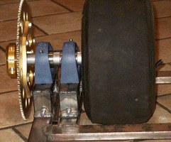
Here I mounted a drive sprocket on one end, and the wheel at the other, with two Plummer block bearings supporting the shaft in the middle. It was a compromise between space and rigidity, but there weren't too many alternative given the motor and ram positions.
Friday 24th January 2003
|
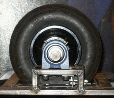
I finished the last of the four Plummer block wheel bearing supports. They were made out of 35mm x 15mm metal box section, and would support the bearing high enough off the chassis for the wheels to protrude through to the ground. There also needed to be some way of adjusting the position of the wheels to allow the chains to be tensioned, so I elongated the mounting holes and made a bracket that secured to one mounting bolt. With the aid of an adjusting nut, the bearing could be moved backwards or forwards until the chain was tensioned. |
 |
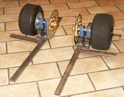 |
I only had a limited amount of metal box section left, but there was just enough to progress with a bit more of the chassis. I built some framework around the wheels; one for the left side and one for the right. Not having the mounting bracket for the flipper ram meant that I would have to wait before joining the left and right sides together. |
