November 2001
Sunday 4th November 2001
For a few weeks I have been communicating with my helpful friend from Southern Pneumatic, Peter, and have been formulating a diagram of the various pneumatic components I think I will need. Below is my first draft of what I want, and Peter has been casting his expert eyes over the components.
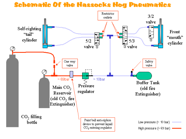
There are several points worth mentioning about this diagram. First, the special paint ball anti-siphon device positioned between the main CO2 reservoir and the pressure regulator. So I am led to believe, this device shuts off the flow of gas if liquid CO 2 enters it. This has good and bad repercussions. The good point is that it prevents the regulator, valves, and cylinders from freezing and potentially being damaged as the robot gets knocked about or turned over. Freezing of pneumatic components can be a real problem, so anything that can prevent liquid CO2 entering the devices and blowing the seals is most welcome. However, once the valve is closed, you are reliant on the gas remaining within the buffer tank to supply the cylinders. If the robot is overturned, then you will only have a limited number of attempts to right it before the buffer tank is empty and you are stranded on your back! The operation of this anti-siphon device is pure speculation for the moment since Peter is still trying to get his hands on one, but it was a device that Gareth told me about when I talked to him about his robot, Wolverine at Wilson's day.
Another point to note is the 3/2 valve positioned at the upper inlet to the front flipper cylinder. This will allow the top half of the cylinder to be depressurised once the flipper is in it's closed rest position. A sensor on the flipper will indicate when it it down, allowing the robot to open the 3/2 valve and depressurise the cylinder. The point of doing this is so that when the flipper is to be raised, the air can escape from the upper cylinder quickly without being slowed down by the piping and restrictors on the 5/2 cylinder. What this means in reality is that the flipper will open a lot faster. With this 3/2 valve closed, however, the movement of the cylinder can be slowed down, and the flipper can be moved to a particular position more accurately if needed.
In addition to the pneumatic components, I needed to add some extra circuitry to the receiver controller to switch the various pneumatic actuators, and sense the position of the flipper. I completed the design of the additional circuitry and included as many of the components left over from my first attempts at a speed controller as I could. This reduced the cost as well as the time to start building. I had a lot of BUZ11 MOSFETs leftover so I used these to drive the valves, and I also had a low performance opto isolator that I used to isolated all the nasty inductive stuff from the micro-controller.
Tuesday 6th November 2001
| I finished the modifications to the receiver controller, which turned out to be quite difficult shoehorning the extra components onto the already busy circuit board. I succeeded in the end, but there is little room now for any further circuitry without major reworking. | 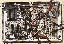 |