November 2002
Friday 1st November 2002
I dropped by my friendly metal workshop to talk over the motor coupling options I had. After bouncing a few ideas around, Bill said he would be able to make me a much stronger coupling than the RS one. He would also make me a couple of sprocket shafts, which would couple directly into a new coupling. He told me to give him a week, and phone back next Friday to see how he was getting on.
Saturday 2nd November 2002
|
I started to build the new motor controller circuit board, which now provided the power for the micro-controller and the radio receiver from the 24 volt battery supply. By the end of the day, I had all the components soldered in, and only had the wiring loom left to do. |
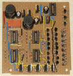 |
I decided to check some parts of the circuitry out before going too far just in case I needed to modify the odd component. I checked out the power supplies to the microprocessor and radio receiver first. I gingerly connected the board to the 24 volt battery supply and then measured the regulator outputs. The voltages were spot on, so I then loaded them up by connecting the receiver and microprocessor in circuit. Things were looking good (e.g no smoke from anywhere) but I checked the temperature of the power regulators with a wet finger. They were both sizzling hot! Not so hot as to de-solder themselves, but hot enough to sizzle the wet finger. I was well within the current rating of the regulators, so I think I will need to mount some heatsinks to keep the temperature down to below boiling point!
Wednesday 13th November 2002
Some heat sinks arrived from RS today, so I put them on the hot regulators and tried the circuit again. The regulators were still worm, but didn't now sizzle when I put a wet finger on them, so things started to look good.
|
I then started to introduce other components into the circuit bit by bit to try them out. I first of all put in the opto-isolators that separated the micro-processor outputs from the MOSFET driver circuits. I connected up the power leads and was just about to poke about in the circuit with the oscilloscope probe when there was a flash and a pop, as the top of the opto-isolator flew off the chip and across the workbench. |
 |
I quickly removed the power and had a close look at the circuit. It took a while, but after close inspection I found that one of the tracks that I had cut on the strip board hadn't cut the whole way through the track. This effectively connected the full 24 volts across the output of the opto-isolator, which quite understandably then acted as a fuse and blew its top. After cutting the track right through this time, I replaced the dead chip with a spare one and then continued to poke around the circuit with an oscilloscope probe.
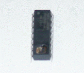
Things were looking good, but I was a bit concerned about the pulses going to the MOSFET driver circuit. The rise time was okay, but the falling edge of the pulses was very slow, and would probably mean the upper and lower MOSFETs would be on at the same time, shorting out the power rails for a short time. On this circuit I had chosen to use "Darlington pair" outputs on the opto-isolators so that I could drive the MOSFET driver circuit into saturation. This I thought would make nice "sharp" pulse edges. However, on closer inspection of the opto-isolators data sheet, Darlington pair outputs have a rise time of about 100 micro-seconds as opposed to the regular ones I had used before that had a rise and fall time of about 2 microseconds. The only option was to go back to the RS catalogue and order some different optos and try again!
Friday 15th November 2002
|
The new optos arrived today, and when I put them in the circuit, the wave forms were almost perfect squares. |
 |
 |
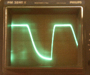
I was now able to test out the MOSFET bricks, but started by connecting only a low powered motor to one brick. I slowly switched things on, and wound up the speed. The motor span okay in both directions, but I noticed it was a bit twitchy, and jittered a lot of the time. I prodded about with the oscilloscope probe, and didn't see the signals from the radio receiver jitter in sympathy with the motor. However, when I looked closer I notice that the signals going from the radio receiver to the micro-controller were switching between 2 and 0 volts. Even though the receiver was fed from a 5v supply, the voltage on the servo outputs was hovering aroud the 2 to 3 volt mark. My thoughts were that my interface circuit didn't provide a high enough level shift, so I will have to redesign it a bit to see if this cures the jitter problem.
.
Saturday 16th November 2002
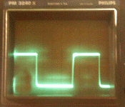
I modified the interface circuits between the radio receiver and the micro-controller so that I could get a square wave that went between 0 and 5 volts. I had to add an extra transistor to each of the three input circuits that I was monitoring. Space on the circuit board was a bit tight, but with a bit of careful moving of components, I made enough room to fit the three extra transistors I needed. When I tested it now, the square wave went between 0 and just over 4 volts, which was a whole lot better that before.
The only problem now was that the signals were inverted because of the extra transistor, so I had to wade my way through the micro-controller software and change a few lines of code to re-invert the signals. With this done, I tried the motor controller again. It was a lot more stable now, and only jittered on a rare occasion. I put this down to the fact that my circuit was not yet enclosed in its aluminium box that would shield if from stray electrical interference. The aerial was also just a small bundle of screwed up wire rather that a long length of wire, so this too may have had an effect. On top of this, it may be possible for me to modify the micro-controller software to ingnore any signals that jump values too much.
Friday 22nd November 2002
I had a closer look at the jittering I was experiencing from the motor controller. I attached the oscilloscope probes to the signal from the receiver and noticed that the signal lost sync every now and then, and they coincided with the motor jittering. It was made better by extending the transmitter aerial so I changed a couple of resistors on the interface circuit to see if that improved things, but it had little effect. As a casual thought I wondered if I simply put all the components in their die cast aluminium box, and screwed the lid down, whether this would shield it from any stray interference it was picking up. The results was dramatic, and the jittering was just about disappeared.
Friday 29th November 2002
|
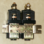
For the last week I have been following up on my old and new sponsors. On Wednesday I received a couple of contactors in the post from Machine Electrics. These were 24v version and could handle 500amps, and would replace my 12 volt version I'd used on Hog 1. |
 |
I also spoke with SKF who were preparing to send some bearings early next week. Steve who I had initially talked to was on a long holiday abroad, but I managed to locate a colleague who was going to take over during his absence.
I had been in communication with Norgren about my new pneumatics, and spent a fair bit of time talking to Tim on the tech support group. I think by Friday we had just about identified the parts I needed. Next week I should find out whether they will finally send the parts free of charge, but the comments they had made so far, led me to believe that this would be so. I will be keeping my fingers crossed! On top of that, they said they would let me raid their bins in Farnham that contained returned goods, or recovered items that were incorrectly ordered. If all goes well I should then be well on my way to starting the Hog. I was going to build the chassis around the pneumatics this time, so have been waiting for pneumatic parts to arrive before cutting up the metalwork in anger.