Why design a controller yourself?
Several people have asked me about my motor controller so I thought it was about time I put finger to keyboard and wrote a few words about it. One of the many questions I'm frequently asked is why did I do it in the first place when there are some very good controllers already available on the market? I reply saying it was because of the winch motors I had at the time that were not particularly efficient, and had a stall current of 500 Amps each. Controllers capable of carrying this level of power were hard to come by and expensive, so finding an alternative would be useful. Very naively I thought that it couldn't be too difficult to make a speed controller given that my professional background was in electronics. I had heard that a few other roboteers had done it already so I launched myself into the project by first doing a bit of research before embarking on the design in anger.
In the following sections I hope to explain some of the theory behind motor controllers and the way I implemented these into the Hog's own controller. I'm under no illusion that my design is the best, but at least it seems to work, and it performs all the functions I need of it.
The explanations I give are my own interpretations of the theories, and expect some people to disagree with the fine detail. However, I have had to adopt a pragmatic approach to the design given the very limited resources I've had to hand. Inevitably during the development life cycle, I've gone through a few ups and down (but a lot more blown MOSFETs) before the system became stable and reliable. I don't profess it to be the best controller by any means, but it has given me a great feeling of satisfaction to have it working now.
The main features of the Hog's Robot controller
- Valid received radio signal detection
- Non-linear joystick control (square law)
- Single joystick steering
- Valid gyro signal detection
- Fail-safe function on all output controls
- Flipper "open" sensor
- Pneumatic valve controller
- Separate "spin-on-the-spot" control
- Gyro enable/disable control
- Option to either force flipper close or return under gravity
- Intelligent flipper return control
- Full H bridge motor control
- 500 amp power capability per motor
- Power supply for RX and micro-controller from a single source
Useful motor controller links
For any of you out there thinking of designing a motor controller too, here are a few links I found particularly useful during my search for relevant information, which are all on my Useful Links page as well.
|
If you want to find out about motor controllers, 4QD is a good reference site and can supply you with tried and tested units. It is also a good site if you want to build your own controller since it explains a lot of the principles involved in motor control. (Phd not required) |
|
|
Vantec is the Rolls Royce of electronic speed controllers, but at a price. They provide tank type control using one joystick as well as simple motor control. They also have info about measuring the characteristics of motors so that you can choose the right controller. |
|
|
If you want some very technical explanations about radio gear, motor controllers, antenna characteristics, spinning weapons, embedded micro-controllers, armour, EMC, batteries, and more, then try Paul Hill's Technical guide to building fighting robots . But be warned, it goes into a lot of details, and is not for the faint hearted. However, it does explain some of the mysteries behind the various parts of a motor controller, and has some nice diagrams to illustrate what wave forms are present where. |
http://homepages.which.net/~paul.hills/ http://homepages.which.net/~paul.hills/SpeedControl/SpeedControllers.html |
|
Impulse are the suppliers of various PC and micro controller cards. They supplied me the Rabbit 2000 micro controller made by Z world that I have used as the main "brain" of the Hassocks Hog. |
|
|
If you are interested in building your own motor control circuit, On Semi have a number of useful documents that will help you avoid some of the pitfalls I didn't manage to avoid. The ones I found particularly useful were " Design considerations for H bridge motor drive circuits ", and " Interfacing power MOSFETS to logic circuits ", but there are numerous others in their document section that are worthy of reading. |
|
|
If you want to build your own cheap, but tried and tested motor controller, then have a look at the Open Source Motor Controller site. Several designers have contributed their ideas, and have come up with a controller that can handle 100 amp per motor. They give you a circuit diagram, a list of materials, data sheets, a circuit board layout, etc., etc.. It's a site well worth having a look at. |
http://www.dmillard.com/osmc/index.html |
Design objectives
The design objectives were to not only make it control the motors, but to make it control the weapons and any other devices on the robot as well. I wanted to give it some intelligence in the form of a micro-controller so that many of the changes that would inevitably crop up throughout its development could be done with the minimum changes to the hardware.
I was also keen to exclude any mechanical devices such as servo motors from the design because I felt they were a liability given the physical shocks the robot was going to receive. After a bit of careful thought, I came up with the main objectives of the design, which were:
- Capable of handling the motor stall current of 500 amps
- Cheaper unit than 4QD's motor controller
- Solid state design with no moving parts
- Flexible configuration with a micro-controller performing most functions
- Opto-isolate "dangerous" high current devices from micro-controller
- Minimum number of parts
- Direct connection of RX to controller without intermediate servos
Background information gathered
There were two topics that I had to research before embarking on the design. Firstly to establish the signals given out from the receiver, and secondly the signals needed to drive the motors. I'll give my interpretation of these subjects here, but if you really want to get into the nitty-gritty, try some of the links I listed above
Radio receiver signals
After a bit of digging on the Futaba website, and a few e-mails to their technical support I established that each channel outputs a series of pulses, the duration of which is proportional to the position of the control lever on the transmitter. The pulse width varies between 1 mSec and 2 mSec, so for example with a joystick fully down, the pulse width is 1 mSec, and with the joystick fully up, the pulse is 2 mSec.
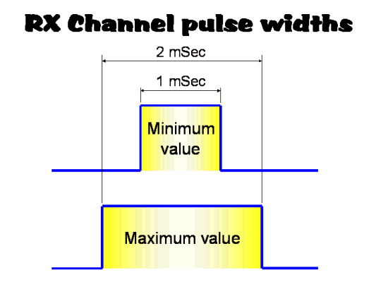
Under normal circumstances when using a mechanical servo, the servo itself decodes these pulses and turns them it into signals that move the servo into the required position. The gap between successive pulses varies depending on the number of channels the transmitter has, and the state of these channels, but typically the pulses repeat between 6 to 12 mSec for a 6 channel system.
Looking further into how each channel's pulses relate to each other, I established that the pulses followed each other serially such that the end of one channel's pulse was followed by the start of the next channel's pulse, as shown in the diagram below.
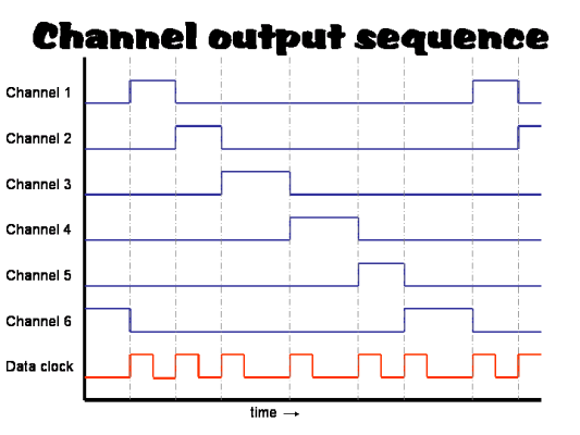
Having established this, it dawned on me that there must be underlying clock stream that triggers each of the channel pulses, this being shown as the bottom trace in the graph. On each positive transition of this "data clock pulse train", it signals the end of one pulse and the start of the following channel's pulse. This being the case, I should be able to establish the pulse widths of all the six channels simply by checking the times between each successive positive transition of the data clock. This has the advantage of only having to monitor one pulse train instead of six, and would reduce my motor controller circuitry and micro-controller routines substantially.
I confirmed that this clock pulse train did actually exist by poking around inside a receiver with an oscilloscope probe until I found this clock stream. The channel pulses turned out to be the outputs of a six channel shift register using D type flips-flops, and the underlying data clock stream was the signal on the clocking input of these flip-flops.
Pulse Width Modulation motor control theory
It is important to be able to control the speed of the robot motors so that you can accurately drive the robot in the direction you want. If you don't have fine enough speed control, the robot is likely to flit left and right and miss your target altogether!
With low powered motors that only consume just a few amps, you could use a variable resistor in series with the motor to vary the current, and therefore vary the speed of the motor. For small motors the resulting power being dissipated in this variable resistor won't be too great and you won't have large heating problems to cope with. This method is often used on small toy models as it is the simplest form of speed control.
When you start to use motors capable of driving heavyweight robots that have stall currents in excess of 100 amps, a series variable resistor will need to dissipate large amounts of power. Apart from having to be a very low value resistor (e.g. in the region of one ohm or less) it is likely to also need extensive heat sinking if you are to stop it glowing red hot! You are also simply wasting energy in heat that would otherwise allow you to keep the robot running for longer periods of time.
PWM duty cycle
A better way of doing speed control is to switch the power to the motor on and off very quickly. The speed of a motor is proportional to the average voltage supplied across it, so if you switch the voltage on and off quickly enough, the motor only "sees" the average voltage. Because of the weight of the motor armature and its inertia, the motor speed won't vary noticeable between each on and off pulse, provided the pulses are short enough and close enough together. To vary the speed of the motor, the duty cycle times of the on and off periods can be varied as shown below.
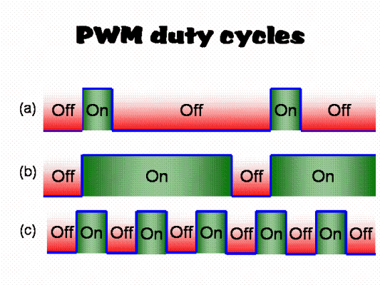
On line (a) the on pulses are quite a bit shorter than the off pulses, so the motor will be moving relatively slowly.
To increase the motor speed you need to increase the on period relative the the off period so that the average voltage is increased. On line (b) this was done by making the on pulse longer while at the same time reducing the length of the off period. The time between the start of each successive on pulse remains the same, but the duty cycle has changed.
On line (c), the period of the on pulse remains the same, but the length of the off pulse is reduced. The effect is to increase the average voltage, but this also means there are more pulses per second than in line (b).
Either methods is valid, but I chose to use the method shown in line (b). The main reason was that I was going to use a micro-controller to manage the pulses, and if I used the method shown on line (c), the processor would have to work a lot harder and faster as the off periods were reduced. With the varying duty cycle method on line (b), there would be less calculations done per second, because there would be less pulses per second.
If the frequency of the pulses is low enough (less than say 20kHz) you are likely to hear the motors buzz as they run. There is nothing wrong with this, it is just the armature vibrating in sympathy with the pulses. You can observe this effect on modern day trains which buzz noticeably as they are driven, indicating that they too are using PWM as a speed control method. In contrast, the the old "slam door" type trains that use resistors to drop the voltage, do not buzz, but are less efficient.
MOSFET devices
The devices normally used to switch the power "on" and "off" are Metal Oxide Semiconductor Field Effect Transistors or MOSFETs. These devices are used because the can switch very large currents under the control of a low signal level voltage. The MOSFETs I use (FQP140N03L) are rated at a continuous current of 140 amps. A nice feature of MOSFETs is that you can simply parallel them up to increase their current handling capacity, so to handle the stall currents of my motors, I simply parallel four of the MOSFETs together to give me a theoretical current handling capability of 4 x 140=560amps. I have my reservations about getting the heat out from these MOSFET quick enough if you maintained this level of current, but if you only peak at these levels for short periods of time, the MOSFETs don't seem to get too hot.
The normal symbol of a MOSFET is shown below next to a relay type equivalent circuit. A purist may not agree that the relay is an exact equivalent circuit, but it does help to show how a MOSFET operates when it is used as a power switching device. Normally a MOSFET is a linear device, but in our analogy I will assume it is non-linear.
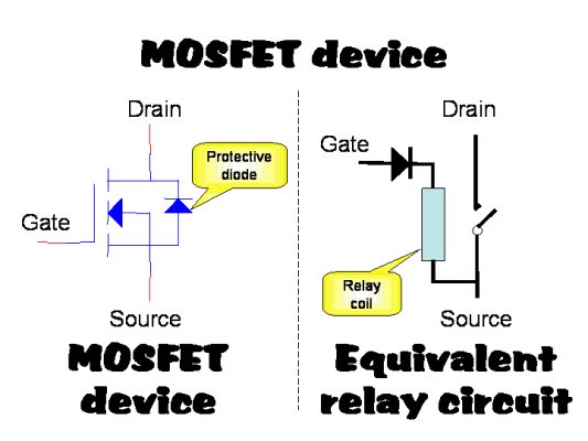
The device switches power between its Drain and Source terminals under control of the signal on the Gate terminal. The threshold at which the MOSFET will switch ON depends on the individual MOSFETs, but for my devices the Gate has to be 2.5 volts about the Source voltage. Any Gate voltage above that "snaps" the MOSFET on faster. However, there is a significant input capacitance on the Gate terminal such that when you want to turn the device OFF again, you will have to discharge this input capacitance, which can slow down the switching time a bit. You therefore have to chose the upper Gate voltage carefully so that you get reasonable ON and OFF switching times.
The MOSFET also has a protective diode between its Drain and Source terminals. This can be used during power regeneration and braking, as described below. However, if this diode has to handle high currents for any length of time, it will tend to overheat the MOSFET and could cause it to fail. This is because a diode has a fixed voltage drop across it in the region of 0.7 volts. With high currents this can produce a lot of power to be dissipated in the device as heat (Power = Volts x Amps). It is often better to actually turn the MOSFET ON if you know it is to carry high currents because the ON resistance of the device is in the order of 0.006 ohms, which will produce considerably less voltage drop, and therefore less power and heat.
H-Bridge driver configuration
To obtain full control of a motor in both a forwards and backwards direction, an H bridge configuration is often used as show below.
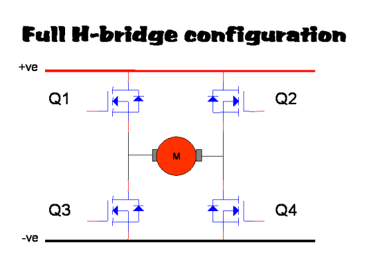
As the name suggests, the MOSFETs are configured around the motor in an H format, such that if Q1 and Q4 are switched on, the motor turns in one way, and if Q2 and Q3 are switched on, then the motor turns in the other direction. If, for some peculiars reason you have Q1 and Q3 on together, or Q2 and Q4 on together, you have a smoke making machine as the MOSFET directly short the power rails together and will most likely self destruct in a matter of milliseconds. This situation is normally called "shoot through" and should never be allowed to happen if you want to keep your pile of crispy burnt out MOSFETs down to a minimum!
Driving ON cycles, and braking OFF cycles
As well as being able to drive a motor using an H-bridge configuration, you can also provide a braking action. The diagram below shows how this is achieved.
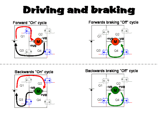
As described earlier, speed control is achieved by applying on and off pulses to the H-bridge MOSFETs. In the top left configuration, MOSFETs Q1 and Q4 are both switched on during the on period and provide power to the motor to make it rotate in a forward direction. During the off period MOSFET Q1 is turned off, and Q3 is turned on in its place, removing the battery from the motor. With the power removed, the motor now acts as a generator and produced an induced voltage across its terminals. The motor now being the source of the voltage means the current flows in the opposite direction through Q3 and Q4, which are both turned on. These MOSFETs offer a very low impedance path for this current, and therefore a strong “motor” force is experienced in the opposite direction to that during the on period. The net effect of this reverse motor action is a braking force acting on the motor in the backward direction.
The bottom left diagram shows the on cycle situation when the motor is driven in the backwards direction by turning on MOSFETs Q2 and Q3. During the off cycle, Q2 is turned off and Q4 on in its place, and again the motor acts as a generator with the induced currents again flowing throw Q3 and Q4 as shown in the bottom right diagram. The MOSFETs once more offer a low impedance path for these induced currents and the net effect this time is a braking force in the forward direction.
Driving ON cycles and regenerative OFF cycles
Instead of providing a braking force, the motor can be used to charge up the battery during the off cycles by changing the way the MOSFETs are turned on and off.
In the top left configuration of the diagram below, Q1 and Q4 are turned on during the on cycle and drive the motor in a forward direction. During the off cycle all the MOSFETs are turned off and the motor acts as a generator producing an induced voltage across its terminals. Depending on the speed of the motor, the induced voltage will rise until it reaches a point where the voltage is more that 1.4 volts above the battery voltage. This being the case, the protective diodes within Q1 and Q4 will become forward biased, and start to conduct. A current will therefore start to flow via Q1 and Q4 to the battery to provide a charging current as shown in the top right diagram. Some braking force may be experienced by the motor as the charging current increases, but this will be substantially less than in the braking scenario described previously.
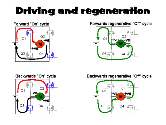
In the bottom left configuration of the diagram above, Q2 and Q3 are turned on during the on cycle and drive the motor in a backward direction. During the off cycle all the MOSFETs are again turned off and the motor acts as a generator producing an induced voltage across its terminals. As before, depending on the speed of the motor, the induced voltage will rise until it reaches a point where the voltage is more that 1.4 volts above the battery voltage. This being the case, the protective diodes within Q2 and Q3 will now become forward biased, and start to conduct. A current will therefore start to flow via Q2 and Q3 to the battery to provide a charging current as shown in the bottom right diagram. Some braking force may be experienced by the motor as the charging current increases, but this will be substantially less than in the braking scenario described previously.
The design
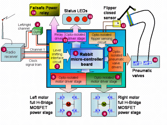
Armed with an understanding of the signals I could detect from the radio receiver, and the way I could provide control signals to the motors for speed control, I was able to put together a block schematic of the robot controller. It has changed a little bit over time, but below is how it looked just after RW Series 7.
The main components
There are 15 main components in the above schematic that together form three groups of items. At the heart of the schematic is the micro-controller that coordinates all the activities the controller has to perform. The signals that pass in and out of the micro-controller do so via Interface Circuits which are those components located within the centre blue rectangle of the schematic. All the other components are the peripheral devices such as motors, pneumatic actuators, etc that control all aspects of the robot. Below are more detailed explanations of each item.
- The micro-controller is an off-the-shelf unit that is made by
Z world and available from
Impulse Ltd. The
main processor is based on the Z-80 instruction set, and there are many
different variations of processor board providing a wide range of functions and
facilities, but the one I chose was the
BL1800 board. The features that attracted me to this
particular version were:

256K of on-board FLASH memory

6 digital inputs

8 digital outputs

14 configurable I/O lines

5 eight bit timers

1 ten bit timer

Watchdog supervisor function

Cooperative multi-tasking C compiler with embedded assembler capability

Programmable and debugged directly from PC using a COM port.

3.5" x 2.5" size
- Level shifting circuit to allow the radio receiver and gyro signals to be monitored by the micro-controller.
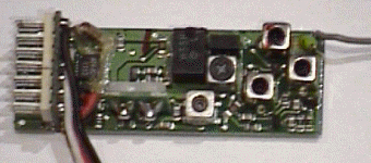
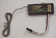
- Radio receiver, modified so that the clocking pulse train is available as well as the channel outputs for the micro-controller to monitor. To see the modifications to the receiver, click here.
- The gyro that provides some driving stability because of the inherent "twitchyness" of a two wheeled robot. This gyro can be switched in and our of circuit my the micro-controller according to the position of one of the transmitter controls.
- Opto-isolated pre-amp driver stage for the left motor power stage.
- H bridge MOSFET power stage for left transmission motors.
- Opto-isolated pre-amp driver stage for the right motor power stage.
- H bridge MOSFET power stage for right transmission motors.
- Opto-isolated driver stage for the flipper pneumatic valves.
- Flipper pneumatic valves.
- Opto-isolated interface for flipper open sensor.
- Micro-switch providing signal of whether the flipper is open or closed
- Opto-isolated driver stage for fail-safe power relay and LED status indicators.
- Fail-safe power relay that disconnects the main power feed from all but the micro-controller and radio receiver.
- Status LEDs showing a CPU "heartbeat", a "valid radio signal" being received, and whether the gyro is in or out of circuit
Micro-controller
The picture below is of a Rabbit 2000 based micro-controller card built by Z world, and sold in the UK by Impulse.
.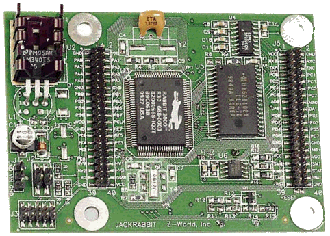
This particular model is the BL1800 board and had a number of features that I considered essential for my robot controller considering the limited test and development environment I had to hand. A primary requirement was that it had loads of I/O lines through which I could control the various peripherals, and determine the state of others. I also needed a number of timers with which I could make accurate measurements of the radio receiver pulse widths. Timers were also essential for generating the PWM pulses to the MOSFETs.
The BL1800 had these minimum requirements, but the more I used it the more I found its other features were extremely useful too. For instance, it has its own on-board power regulator so could be powered from a wide variety of power sources. You needed no more that to connect it to the serial port of your computer to program and debug it, and the unit came with its own software that included an editor, a C compiler (Z world's dynamic C) and a debugger.
Z world's particular version of C has a multi tasking environment that makes it very easy to run background tasks such as, in my case, monitoring the radio receiver for errors, while in the foreground it allowed you to manage commands for the weapons and motors. If you needed to react very quickly to events, you can even write interrupt driven machine code routines and embed them directly into your C code, which is the method I used to measure the radio receiver pulse widths.
All in all the Z world micro-controller board was ideal for my application because I had limited resource and limited funds. It was a very compact unit, but full of features and functionality.
Power Supplies
On Hog 1, I used three sets of batteries to power the electronics. I used Sealed Lead Acid (SLA) batteries to power the motors, a pack of NiCads to power the radio receiver, and a separate pack of NiCads to power the micro-controller. When I revamped the robot controller for Hog 2, I decided that I wanted to power everything from the same source as I felt that having different battery packs was a liability. If one failed the robot would be immobilised, so reducing the component count should make the unit more reliable.
To get more driving power I was going to over-drive the 12 volt Bosch motors at 24 volts, so would have to generate all the other supplies from a single 24 volt battery supply. I needed 5 volts for the radio receiver, 12 volts for the micro-controller, and another 12 volt supply for the interface board. Components like the pneumatic valves and motors I would use the 24 volt battery supply direct. Providing these supplies was done using well established circuits and well know voltage regulators like LM05 which are available from suppliers like RS components.
There was only one other supply that I needed, and that was a MOSFET high side gate drive supply. This was a 36 volt supply, but it didn't need a great current carrying capacity. The reason for this odd high side supply is as follows.
There are two ways of designing a full H bridge motor driver using MOSFETS. One is to use complementary MOSFETS where you have N Channel types switching the -ve power supply, and P channel types switching the +ve supply. The other method is to use the same MOSFETS throughout.
There are pros and cons for each type, but I opted for using all the same types because I felt the ON impedance Rds(on) needed to be as low as possible to reduce wasted power and heat in the MOSFETS. P channel devices tend to have higher impedance and different switch on and off times, so would tend to heat up more, and waste more power. Different switch on and off times would make the circuit more prone to shoot-through (both upper and lower MOSFETs on at the same time shorting out the power rails) so I chose to us all N channel devices, and what's more they tend to be cheaper too. The trouble then is generating the gate signals.
With complementary devices you use positive going pulses on the gate of the N channel devices to turn them on, and negative going pulses on the gate for the P channel devices. When using all the same devices you need to produce positive pulses above the source terminal voltage, which for the top MOSFETS means a voltage above the positive supply rail, hence the need for a 36 volt supply
The way I decided to do this was to use a small DC to DC converter to provide a 12 volt supply, and then reference this to the +ve supply rail to give me the relevant gate driving supply voltage of 36 volts. You have to be careful about which DC to DC converter you use because some will short themselves out if you reference their -ve output to their +ve input supply. You need a type of converter that has a completely isolated output stage otherwise the device will last less that a second before blowing up. Needless to say I learnt the hard way about which devices had isolated output stages, and which ones hadn't.
As part of the fail-safe function I only had the radio receiver and micro-controller power supplies fed directly from the safety link. All the other supplies had the power fed through a fail-safe relay that was only switched on by the micro-controller once a valid radio signal had been received. In this way all weapons, motors and actuators would be without power if no valid radio signal was present.
The H Bridge MOSFET power stage
The MOSFETs were the devices that switched the power through to the motors, and although could handle high currents, needed to be mounted on suitably large heat sinks, and fed with suitably large cables. I was going to overdrive the 12v 630 Watt Bosch motor at 24 volts, which meant that the stall currents could rise up to 500 amps (in theory). The MOSFETs I was using were FQP140N03L and supplied by Fairchild. Each could handle 140 amps so I would therefore need to parallel up four in each of the H bridge branches in order to handle the full stall current. I was a bit suspicious about being able to extract the heat quick enough from such physically small devices, but I would hope not to be drawing that sort of current for long periods of time. And in any case, I didn't think the batteries could supply 500 amps to each motor without their terminal voltage sagging a bit.
The Hog 1 MOSFETs were mounted on commercially bought heat sinks that made it very difficult to connect the power supply cables to them without leaving them vulnerable to mechanical damage because the lack of physical support of the leads. With the Hog 2 design I wanted to build a solid structure that would not only act as a large heat sink, but would also provide power "bus bars" supplying power to and from the MOSFETS. After a lot of head scratching I came up with the following design.
| The bottom plate in the adjacent photo is where the MOSFETs are all bolted to, and acts as the main heat sink. This plate holds all the MOSFETs needed for a complete H bridge circuit. The strips in the middle of the photo supply the +ve and -ve power supplies to the MOSFETs, hence they connect to all the MOSFETs in a row. The top "ring" plates are the outputs to the motor. | 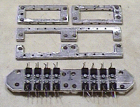 |
| Here is a photo of the fully assembled MOSFET "brick", together with large capacitors. These are mounted on the assembly so that they are physically as close to the MOSFETs as possible, and able to smooth out any spikes the MOSFETs produce as quickly as possible. | 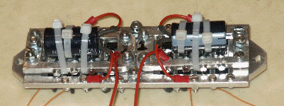 |
The MOSFET leads that carried the main current flow were clamped to the bus bars with screws, which makes it easier to replace any devices that blew up. The low current requirement of the "gate" leads meant that I could solder the wires to the leads. Only having one lead to solder per device make the process of changing damaged devices a whole lot easier than with the early design where all the leads were soldered.
Interface board
All the interconnections between the micro-controller and the peripheral devices went via the Interface board, as shown below. In the picture it is without its chips in place, and before the flying-leads to the micro-controller had been attached, but hopefully you can see that it is not too densely populated despite this. This is because its main function it to simply pass signal to and from the micro-controller, the complex functions being handled by the micro-controller within the software, rather than from the hardware.
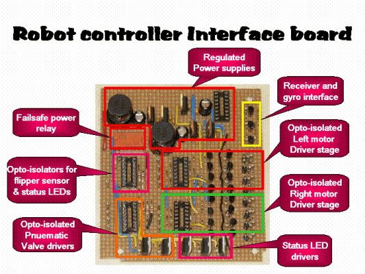
Most of the interface circuits provided a simple voltage "level shift", but the motor driver stages required a bit of careful thought. Although the MOSFET gate inputs had an extremely high impedance, they also had a noticeable capacitance value. When you parallel four of these up per H bridge branch, the capacitance starts to become significant, and you have to make sure that the charging time of this capacitance does not adversely affect the turn on and off times of the MOSFET too much. Each gate driver stage therefore consists of a push-pull transistor pair to try and drive the gate voltage up and down as fast as possible. In addition I wanted to ensure that the chance of "shoot through" with both the upper and lower MOSFETs being on at the same time was kept to a minimum. I therefore wanted to turn the MOSFETs off slightly quicker than I turned the others on. To do this I put two small resistor networks between the push-pull transistors and the MOSFETs gates (10 ohms and 100 ohms) that would ensure the voltage rise time was slightly slower than the voltage fall time. Each of the two networks were driven via diodes so that the slower network was used during turn on, and the faster one during turn off.
RX decoding
The standard radio receiver has a three pin connector for each of its channel outputs, plus one for providing power to the receiver. As explained earlier, I could have monitored all six outputs to establish the different channel states, but this is fairly wasteful in terms of hardware components and software programing. A better way is to monitor the underlying clock pulses in the receiver, and from this you can establish the state of all six channels from one data stream. The only problem is then synchronising the clock pulses with the channels they relate to, but by checking the state of the channel one connector, say, whenever a clock pulse is detected, you can synchronise each of the pulses with its respective channel number.
I therefore needed to locate the main clock pulse train from within the receiver and extend this out for the micro-controller to monitor. This together with a connection to the channel one connector would be all I needed to monitor the signals
|
Gyro monitoring
I wanted to include a gyro in the steering arrangement because two wheel drive robots are notoriously "skitty" when it comes to steering. You often see robots over or under steering and missing their target completely. This is usually because they have no gyro involved in their system to maintain the robot in the desired direction.
Normally a gyro in connected in series between the left/right channel output of the receiver and the left/right steering motor or device (as shown in the schematic above). The theory being that the drivers desired direction is fed through from the receiver to the gyro, which then varies this signals accordingly as it experiences the turning motions of the robot. If it detects over-steering, it backs off a little bit. If it detect under-steering, the gyro increases the turning signal a bit. The net result is the robot keeping to a steady curve during maneuvers.
If the robot gets inverted, or you connect the gyro the wrong way round however, the effect of the gyro is then to make the robot completely uncontrollable. Instead of adjusting the steering to keep you going in the desired direction, the gyro will send the robot spinning in ever tighter circles as soon as you stray off a straight line direction.
In the Hog's robot controller I had to connect the gyro to the channel on the radio receiver that I had chosen to use for the left/right control. I was using the right hand joystick as the driving joystick with the vertical direction as the forward/backward control, and the horizontal motion as the left/right control. The left/right control turned out to be the first channel on the receiver, so I connected the gyro input to this channel. I then fed the gyro output to the micro-controller for it to monitor separately from all the other radio channels. In this way, I could decide from within the software program when to use the signals from the gyro, and when not to; the hardware wouldn't change. I had a spare control on the transmitter so decided to use this to inform the micro-controller when to use the gyro output as the steering signal, and when to take the signal directly from the radio receiver. With the control less than half way, the gyro was ignored, and with the control over half way, the gyro was used.
Pneumatic valve drivers
The driver circuit for each of the pneumatic valves was a fairly conventional circuit consisting of an opto-isolated MOSFET that feeds the 24 volt power supply through to the valve. I put clamping diodes across the valves to shunt out any back emfs the solenoids might generate when turned on and off.
Flipper sensor
I wanted to make the flipper re-arm itself once it had been fired so that it would be ready to fire again immediately it had returned to a closed position. I had designed the pneumatics such that it had a 16 bar feed through to open it, but a 2 bar feed to close it again.
I had also decided that the left hand joystick's vertical movement would be used to fire the flipper. In its upper position, it would fire the flipper open, and in its lower position it would force the flipper closed. It its middle position its action would depend on where the flipper was at the time. If the flipper was down, the pneumatic valves would be all idle and ready for a fast flip open. If the flipper was not closed then the "down" valve would be operated until the flipper was closed, after which the valves would all be set to idle again. Having the controller re-arming the flipper automatically would mean it would be ready to open as quick as possible. To do this, however, it would have to sense when the flipper was open or closed. I did this my positioning a micro-switch in a suitable position under a bolt on the flipper such that it would operate the switch only when the flipper was fully closed. This micro-switch was fed through to the micro-controller via an opto-isolator so that the position of the flipper could be detected by the controller.
Flipper buddy box
As well as being able to control the flipper from the radio transmitter, I wanted to have an alternative method of firing the flipper too. It is quite a task to drive the robot as it is, so if someone else in the team could be in charge of operating the flipper, it would be a great help. I thought initially that I could use the "training" connector at the back of the transmitter, but had to abandon the idea because that simply transferred all the controls to another transmitter rather than just some of them.
In the end I took the back of the transmitter and intercepted the wires going to the left hand joystick and fed them out via a remote/local switch to a socket that I fitted to transmitter's rear cover. I also intercepted the wires from the "landing gear" switch and fed them out to the same socket. With the remote/local switch in the local position, all the transmitter controls would operate as normal. With the switch in the remote position, the buddy box that I connected to the rear socket would take over control of the left hand joysticks vertical action, and the landing gear switch.
|
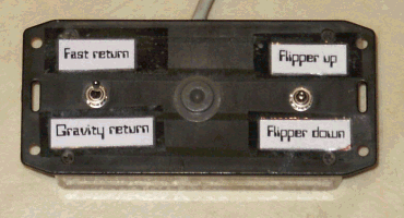
Here you can see the buddy box has two switches on it. The right hand switch is a three position switch, normally sprung loaded to its centre position. This takes the place of the left hand joystick that fires the flipper up and down. The switch on left hand side is a two position switch that performs the function of deciding to either allow the flipper to close under gravity after firing, or to force it closed by feeding the 2 bar feed to the "close" valve. Effectively it tells the controller to either monitor the "flipper closed" sensor and act accordingly, or to ignore this sensor and assume the flipper is always re-armed and ready to fire again. |
 |
Software features
The micro-controller was the "brain" of the robot controller, and as such it had to do a lot of tasks to do. Some were going to be extremely time critical such as accurately measuring the width of the receiver pulses and sending pulses to the motor drive MOSFETs, while others could be fitted in as and when time allowed. I was hopeful that my choice of micro-controller was a good one, but it was only because of a few pertinent feature that the micro proved that it could handle all the tasks I needed it to.
The critical features of the micro-controller were:
- Being able to write interrupt driven machine code routines that could be directly embedded into the main C program
- Interrupt capability from I/O lines as well as presetable timers
- Interrupt priority assignable to individual events
- Pre-loadable timers and data port registers
- Cooperative multi-tasking operating system
- Real time clock source
Interrupt routines
The first program I wrote was an assembler routine that measured the radio receiver pulse widths. The receiver's master clock train was connected to an input to the micro that could be configured to generate an interrupt on each positive going edge. When this happened the interrupt routine immediately went to the real time clock and stored the current time. It would then retrieve the time it had stored from the previous interrupt and take it away from the current time to calculate the duration of the last pulse. The particular speed of the real time clock allowed me to measure 28 different levels as a channel went from fully off to fully on. I chose to give myself a bit of headroom so decided to work with a resolution of 26 different values for each channel.
Knowing the resolution I now had to work with, I decided to create a look-up table that would hold information needed to generate the motor MOSFET pulses. There would be 27 different entries in this table(13 positive, 13 negative, and one zero), each of which would hold the information for a particular speed. The values would be count down timer values, port state assignment values, and port masking information to ensure only those MOSFETs required were changed.
The next routine to write was one that would take a set of values from this motor speed look-up table and use them to pulse the MOSFETs at the appropriate duty cycles.
On the micro-controller board there was an eight bit I/O port that you could preload with the values you wanted the port to take once a pre-loadable timer had counted down to zero. This was ideal for motor control because you could set the timer to count down the duration of, say, the OFF pulse, at which point it would then automatically set the port outputs to the new ON state. All the outputs would switch at the same time thereby preventing any chance of "shoot through" occurring. The pulses would occur at exactly the right time because the new port values were loaded automatically as the timer reaching zero, there was therefore no delay while an interrupt routine worked out what settings the port should have. When the timer had reached zero, it not only loaded the port with the new values, but it also loaded a new timer value into itself and then raised and interrupt. By keeping a track of which pulse period had just timed out (ON or OFF pulse) the interrupt routine could then load a new values into the timer and I/O port pre-load registers ready for when the timer next reached zero. As long as you didn't set the countdown timer values too small, the pulse would happen at exactly the right times, leaving enough time between these interrupt routines for the rest of the tasks to take place.
Ideally you would want to make the pulses as short as possible and repeat them as quickly as possible so that the motor would not "buzz" too much and ran smoothly. By trial and error, and by using different timer values I ended up using a minimum pulse width of 78 microSec that repeated every 1.17 msec. You can hear the motors buzzing a bit because this repeat rate is equivalent to a signal of about 800hz, which is well within the the human hearing range. But this was the smallest pulse width I could get away with without the interrupts arriving too close to each other and becoming re-entrant. (a new interrupt occurring before the old interrupt routine had finished.)
I had thought that I would give priority to the motor pulse interrupt routines but later on had to change this and give the radio receiver pulse measurement routine priority. There was enough slack in the motor pulse duration to wait if necessary for other events to take place. Measuring a pulse width could not wait without it causing jitter to result.
Pulse jitter
Measuring pulses inherently introduces jitter into measurements because pulse widths are very unlikely to be exact multiples of the real time clock, as shown below.
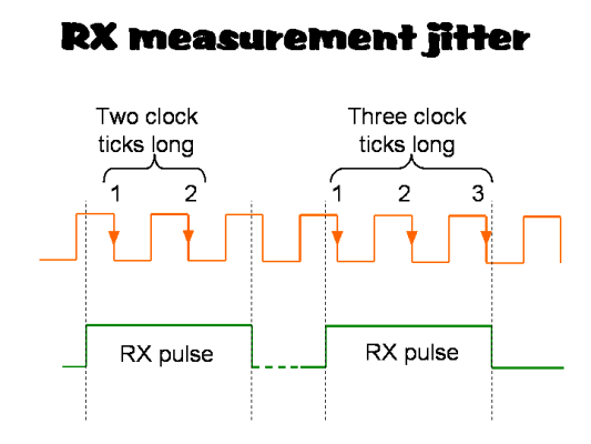
Here the green line represents two receiver pulses of exactly the same width, but depending on when they occur, the interrupt routine would count a different number of negative going clock pulse edges. The result is that even though consecutive pulses may have exactly the same duration, the measurements you take will jitter between two values. In the example above, the number of negative going clock pulses will be either 2 or 3. The solution is to continually check consecutive values, and only register a new value if it changes by more than two.
Motor speed routine
Once I had the timer interrupt routine running that continually generated pulses for the MOSFETs, it was a relatively easy task to then write a high level routine to select the speed you wanted the motors to run at.
The motor speed look-up table contained 27 lines of variables; one for each speed setting in the range of -13 to +13 with the middle value of 0 holding the motors at rest. The interrupt routine would use one line from this table, and would hold these values in its own area of memory. The task was then to select the appropriate line of variables from the table and to then load these into the memory area the interrupt routine used, making sure that interrupts were disabled whilst the move was taking place.
The motor speed routine could then be called when desired while passing over two parameters; one to identify the motor you were concerned with, and the other to select the speed you wished it to go at.
Receiver pulse validation
As part of the fail-safe functionality the robot controller had to provide, I had to somehow detect when the receiver had lost contact with the transmitter. When loss of signal occurs, the receiver could act in one of two way. Firstly it might simply stop sending out pulses to any of its channels, which in my mind was the most obvious situation to occur. Alternatively it might pick up any stray airborne interference and sent out a random streams of pulses, some of which would have valid durations, and others not.
Initially I had only considered the situation when pulses ceased being sent out, so set up a two stage process in order to check for the lack of pulses.
I created a variable called failsafe_rx that was reset to zero by the interrupt service routine each time a new pulse arrived. Then in the main program, I set up a background routine that regularly checked failsafe_rx every 40 mSec or so and added one to it. Under normal conditions failsafe_rx would only increment by a small amount before a new pulse was received and it was set back to zero. When the pulses ceased and failsafe_rx was not reset during the interrupt service routine, it would be increased during the background task until it reached a value above 112, which I considered high enough to indicate there was no valid signal being received. The threshold value was chosen by trial and error, but was a compromise between not waiting too long before detecting signal loss, and falsely triggering when the signal was still valid.
During tests it didn't' take long to find out that a loss of pulses were not the only possible outcome when the transmitter was turned off. What happened was that instead of the receiver channels becoming steady, they became extremely erratic and jumped from one extreme to another. It was only when I put an oscilloscope probe on the channel outputs did I realise what was going on. With the situation now understood, I had to figure out how to determine when too many of the pulses were outside the normal tolerances.
I created another variable ber that would again be used in a two stage validation process. During the interrupt routines when a new pulse had just arrived, a check was made to see if the pulse had a valid duration of between 1 and 2 mSecs. When it was within tolerance ber was decremented by one, and if it was outside this range, ber was incremented by one. If ber was already zero, then it wouldn't be decremented any further. Likewise if ber had reached a maximum level of 35, then it wouldn't be increased beyond this point. The second stage process was another background routine run within the main program that kept an eye on the value of ber. When the value rose above 10, I deemed this to be high enough to indicate the signal was invalid. However, ber could continue to rise until it reached a value 35, which means for the signal to become valid again, ber would have to be decremented back down to 10. The net result is that there has to be a far greater number of in-tolerance pulses received than out-of-tolerance ones before ber drops below 10 and the signal is deemed to be valid once more.
With these two pulse validation methods in operation, a consistent result was obtained, which meant I could implement a stable fail-safe function for the robot.
Fail-safe operation
With a robust and reliable method of detecting when the transmitter signal was lost, I was now able work on a fail-safe function. I had established that the readings I could detect for each receiver channel were within the ranges of -13 at the lower end, and up to +13 at the top end; zero being the mid position value. I created a look up table with six fail-safe entries in it, one for each of the channels. These entries were the values the respective channels should have under fail-safe conditions. For controls like the forward/backward control, the fail-safe value would be zero. e.g. at rest. Likewise for the left/right control the value would be zero. For the weapon values they might take a value of -13 or +13 depending on how I wanted the weapons to be safe.
The fail-safe process was then one of detecting when the receiver signal had become invalid, and to then slowly ramp the current channel values to the fail-safe values. Again this was a background task running in the main program that continually checked the variables failsafe_rx and ber. Once an invalid signal had been detected, the individual channel values were incremented or decremented as necessary until they reached their respective fail-safe values contained within the look up table. The values were checked every 40 msec, so in a worst case scenario when a channel at one end of its range needed to be ramped to the other end 26 increments away, it would take just over a second to get there. e.g. 40 mSec x 26 =1.04mSec.
Once all the channels had reached their fail-safe values, the fail-safe power relay was turned off, which in turn removed power from all devices except the micro-controller and radio receiver, in effect completely immobilising the robot until a valid signal was again detected.
The main program
The main program was relatively small compared to the total size of all the routines needed to run the whole controller. The main routine consisted essentially of two parts. The first part contained the background tasks that needed to be run continuously to check for valid radio signals, light the status LEDs, and handle the fail-safe situation. These were routines that ran endless loops, but because of the multi-tasking operating system could be started and then left to run. At regular points they would "yield" to other routines as part of the cooperative multi-tasking environment, so it was relatively easy to bundle all the background tasks together and then forget about them.
The second part of the main routine read all the channel values and then went through each one in turn deciding what effect each would have on the motors, weapons, etc. Some of the features worthy of note where how I implemented the steering, and how I decided when to use of the signal from the gyro.
Steering control
I had early on decided that I wanted a single joystick control for forward/backwards and left/right control rather than using one joystick for the left motor and one for the right motor. It also meant that I could implement the gyro stabilisation a lot easier too.
To achieve the single joystick steering I had to first note the value of the left/right channel. If this was zero, then the robot needed to go in a straight line with both left and right motors running at the same speed. I therefore had to read the value of the forward/backward channel and then send this value to the left and right motor speed routines.
When the left/right channel was not in the centre, I would reduce the motor speed on one side so that the motors would run at different speed, thereby causing the robot to turn. The way I decided by how much one motor speed should be reduced was to work out the ratio of left to right the joystick was in, and to then reduce the motor speed on that side by the same ratio.
So for example if the joystick was to the left at position -7, there would be 6 divisions to the left (13-7), and 20 to the right (7+13). The ratio would therefore be 6/20 =0.3. If the forward/backward channel was say 10, then the left motor speed would be set to 10x0.3=3, while the right motor would be set to 10.
Selecting the gyro
I had a spare radio channel available so decided to use this as the "gyro select" control to either switch the gyro into circuit, or leave it out. It was a simple task to implement because all I had to do was look at the "gyro select" channel, and if the value was less that zero, I would use the left/right channel in the steering calculations. If on the other hand the "gyro select" channel was greater than zero, I would use the gyro channel in the steering calculation. At any point while driving the robot I could switch the gyro in and out of circuit as I felt fit.
Non linear motor speed control
One advantage of using a micro-controller in the speed control function is that you can change the characteristic of the speed curve. In other words, moving the joystick forward half way doesn't necessarily mean the motors have to run at half speed; they could run fast or slower if required.
In my motor speed look-up table I implemented a square law relationship between the joystick position and the resulting motor speed. I did this so that I would have finer control at lower speeds, and coarser control as you approached full speed. The idea was to allow you more accurate steering control as you moved off from rest, but once you were moving at a pace, the fine control was not so important. I could implement all sorts of strange relationships, but have stuck with a simple square law one for the present.
Non linear motor speed control
|
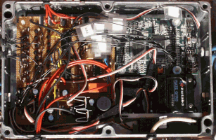
The complete motor controller is shown here. On the left is the interface board, and at the top right is the micro-controller. Underneath that is the gryro, and below that is the radio receiver. With all the wires (and their labels) it makes it a bit difficult to see what is what! |
 |
