June 2007
Friday 1st June 2007
Over the last few weeks I have been collecting suitable items for Hog 3. Some have been old items that I aquired whilst building Hog 1 and 2, while others I have bought specifically for the new Hog.
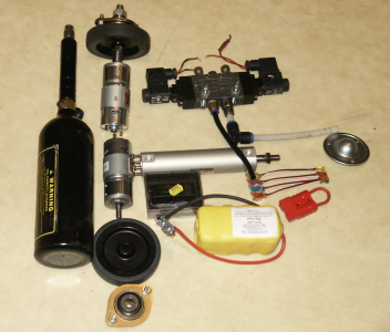 |
The main items are a paint ball bottle with regulator (far left), 2 drill motors, trolley wheels and bearings, (left centre), one ram, 5/3 valve, receiver, and NiCad batteries, (centre), and one safety link and roller ball (right). I had done some intial research before buying the drill motors and NiCads from technobots, so these should be roughly the right size. I had also used my flipper calculator spreadsheet to work out how big the ram needed to be that I would use to flip a 12kg weight, based on the pneumatics running at 10 bar pressure. |
||
|
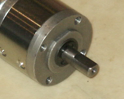
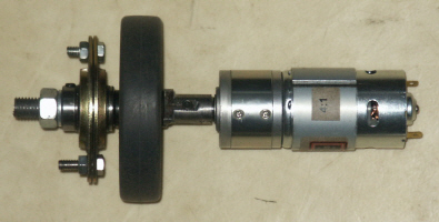
One of the first things I decided to tackle was how to fit the trolley wheels to the motor shafts. The drill motors had a 4 to 1 gearbox fitted to them, so I would be able to fix the trolley wheels directly to the motor without any further gearing in between. I knew I had to make some kind of shaft to fit the wheel to, but there were a couple of problems that I had to overcome first. The first was how I was going to lock the trolley wheel to this shaft, and the second was how I was going to lock the motor spindle to this shaft too. |
|||
Sunday 9th June 2007 |
|||
|
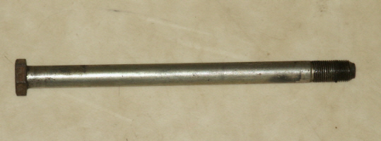
I found an old swinging arm bolt lying around the garage that was going to be ideal as the source material for the axle. I had recenly inherited a small lathe from my father, so would be able to turn this bolt down to the correct size myself rather that give the task to an outside company. |
 |
||
|
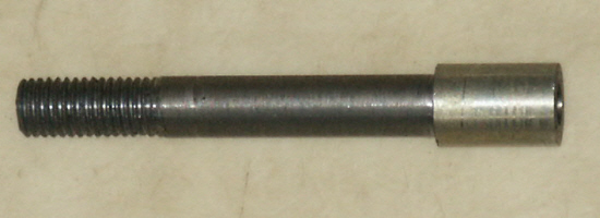
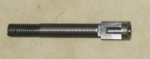
After the first phase of machining, the shaft was cut to length and had the right hand section machined with a hole that would accommodate the motor spindle. The middle section was machined to fit the trolley wheel and then the plummer bearing, while the left hand section was threaded so that a bolt could hold the bearing and trolley wheel in place together. |
 |
||
|
The next stage was to file a flat on the motor spindle section of the shaft. It was filed down to the level of the flat on the motor shaft so that a flat peice of metal could then be welded in place, therby locking the motor spindle to the wheel shaft |
 |
||
|
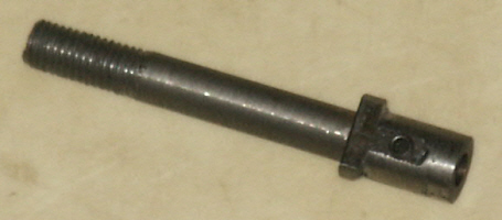
Here you can see the flat metal plate after it has been welded in place, and machined back to the profile of the shaft. I had tapped a thread in the middle of this plate and fitted a grub screw that would hold this shaft in place on the motor spindle. The plate not only covered the motor spindle section, but was extended a couple of millimeters into the trolley wheel section of the shaft. In this way it could locate onto the trolley wheel an lock it onto the shaft. |
 |
||
|
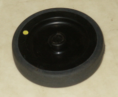
You can see below where I cut a flat into the middle part of the trolley wheel so that the extended plate would fit snuggly against it and lock all the items together. |
|||
 |
 |
||
|
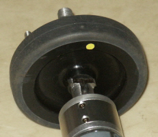
Here is the finished item with the plummer bearing, trolley wheel, and motor all in place on the shaft. |
 |
||