Flipper calculator spreadsheet (version 5)
Designing an effective flipper takes more than just scrounging any old pneumatic parts, bolting them together, and then attaching them to a flipper. You might end up with a very good flipper, but the chances are you will end up with a "limp lifter" rather that a "feared flipper".
To help me improve my own woefully inadequate flipper, I wanted some way of simulating its performance before building it. I needed to check its performance first, before wasting money buying the wrong parts. As a benchmark, I wanted to know how high my flipper would throw another robot, but after trawling the Internet for some form of simulator, I gave up and set about creating a spreadsheet for myself.
"Flipper calc" is the result of a few months work picking peoples brains and surfing pneumatic suppliers and gurus. I won't pretend that "Flipper calc" is a 100% accurate simulation, but none the less it gives a close enough indication of flipper performance. In any case, the theory may be all well and good, but there are practical aspects such as curvatures of pipes, the type of connectors used, etc, that will affect the performance of your flipper too. Once the theory has identified the parts you need, the practical aspects will have to be addressed as well.
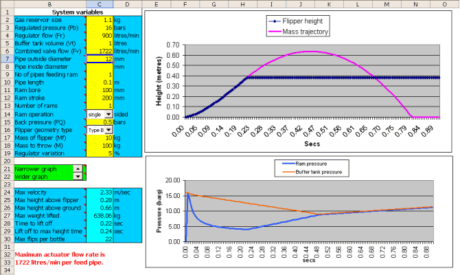
Version 5 now includes a plot of the pressure in the buffer bottle as well as the pressure in the ram. The benefit of seeing both on the same graph is that the closer the two are together, the slower the flow of gas is into the ram. When the two are on top of each other, it will make no difference what flow rate your valve has, the flipper will not operate any faster. This can be useful in determining the flow rate your valves will need to get the maximum speed from your flipper.
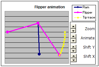
This new version still includes a schematic of the flipper that not only allows you to visualise its shape from the given values, but also allows you to animation of the flipper in small steps as it extends. You can also zoom into the schematic, as well as shift it left and right, and up and down.
Taking all the theory into account, I would suggest that any roboteers wishing to use "Flipper calc" follow the guidelines below. Any comments, good or bad would be most welcome. E-mail me at feedback@hassockshog.co.uk
1. Download Flipper calc
You can download the "Flipper Calc" spreadsheet in uncompressed or
zipped format. Choose the file you want, then either click on the link, or
right click and choose "Save Target As..."
Uncompressed Flipper calc
spreadsheet (377k)
Zipped
version of Flipper calc spreadsheet (116k)
2. Flipper type
Decide on the type of flipper you intend to use, which will be one of those below. The basic difference is the position of the ram in relation to the flipper tip and pivot, and the position of the fixed end of the ram in relation to the flipper pivot. These four types will cover all possibilities for fixed shape flippers. Despite the varying flippers you see around, the underlying geometry of fixed shaped flippers will always fall into one of these four types.

|
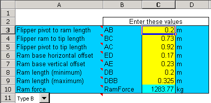
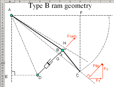
Enter the measurements you want to checkout into the "flipper geometry" sheet. To help you identify the measurements to enter, there are four detailed schematics within the spreadsheet, each on a sheet of their own. |
 |
|
The letters enable you to define each flipper component, so for example member AB is the distance between the flipper pivot and the point where the ram connects to it. |
 |
|
On the flipper "geometry sheet" there is now a schematic representing the main elements of the flipper. This is useful to visualise how the component might fit together in the robot. If you choose a value that say, makes it impossible for the ram to fully extend, then the yellow trace will have a kink in it. You can also check out the action of the flipper by clicking on the up and down arrows, which will make the flipper step through from its upper and lower positions. |
 |
3. Pneumatic variables
|
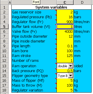
Decide on the pneumatic parameters you wish to use, such as pressure, ram size, valve flow rate, buffer bottle size, etc., and enter these into the "Pneumatic components" sheet. |
 |
4. Check performance
With the values you have entered in the spreadsheet, look at the graphs on the "Flipper geometry" sheet, and the "Pneumatic components" sheet. If you are not happy with the performance, change some of the parameters and see what happens.
|
The graphs I have found particularly useful are the "Flipper height" graph and the "Ram pressure" graph. From these you can see how high the flipper will throw objects, and how quickly it reaches its full height. You can also see how the pressure in the ram changes over time. It's useful to see how the valve flow rate affects how quickly the rams reach full pressure because this will affect the performance of the flipper in "quick fire" situations. |
 |
I hope you find "Flipper Calc" a useful and worthwhile tool, but whether you thinks it's good or bad, any comments or suggestions would be most welcome. E-mail me at feedback@hassockshog.co.uk