March 2003
Thursday 6th March 2003
|
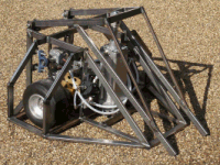
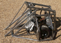
With the chassis base now complete, I worked on the upper chassis structure, which was following in the Hog 1 style with vertical lower sides, and angled upper sides. I trimmed the motor brackets back a bit and then bolted them to the upper chassis to that I could now fit the transmission system of sprockets and chains. |
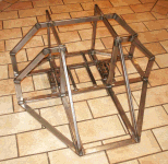 |
Things we looking quite good, but it was now becoming a bit big for the work bench and a bit heavy to keep shifting around. What I needed was to find some room on the floor in the rest of the garage, but for the moment the Hassocks Hog 1 was still occupying this space. Over the coming weekend I will have to rearrange things to see if I can get some more floor space.
Sunday 9th March
This weekend was quite productive with me first managing to shift the Hassocks Hog 1 into a corner of the garage, thereby leaving a space on the floor to put Hog 2. Because Hog 2 was quite a bit shorter that Hog 1, I could rotate it without it snagging on any other object in the garage. This made it a whole lot easier to work on the flipper, which was now the focus of my attention.
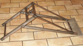
I took a few more measurements of the chassis and entered them into my flipper calculator to get the best geometry. According to the spreadsheet, it should be able to lift just under 600kg at the flipper tip, and toss a 100kg weight 40cm into the air. This seemed about the best performance I could achieve given the chassis measurements, so I spent the rest for Sunday building the flipper itself. By the evening it was 90% there with most of the structure cut and welded together. All than remained to do now was fit a shovel end of some sort at the tip, and to add a of small lever at the rear that would be used as a self righter should the Hog be stranded on its backside.
Monday 10th March 2003
|
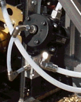
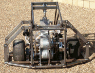
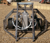
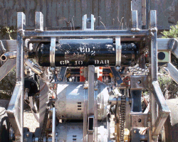
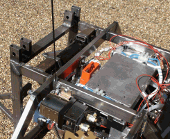
I looked at where I might locate the pneumatic valves so that they had as short a length of pipe as possible from the valve to the ram, and with the smoothest of curves as I could manage. This would hopefully ensure a smooth flow of gas and make the maximum use of the gas as possible. I looked at mounting the high flow rate valves first, as these would need pride of place over all the other components. I managed to position them very close to the ram by bolting them to the upper chassis struts. Since they valves where high flow rate with a working pressure of 16 bars, they were operated with air, so I needed another set of valves to provide them with gas. These were a lot smaller, and I managed to site them right next to the high flow rate valves. |
 |
Wednesday 12th March 2003
|
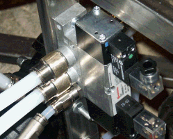
I received some more pipe adapters from Norgren, so looked at how I could connect up all the valves together. I wanted to use 12mm tubing because this was the largest piping that could handle 16 bars, and would offer the least resistance to the gas flow to the valves. The problem was that with 12mm adapters, these would physically be too big to fit in the adjacent ports of the valves with out touching each other. However, if I filed the hexagonal exterior of the adapters, this would reduce the diameter just enough to screw them into the port holes. Luckily these adapter had a hexagonal interior where you could use an alen key to tighten them up so filing the adapters to a round exterior wasn't going to cause problems bolting them to the valves. |
 |
Thursday 13th March 2003
I received some sample plastics from Display Development Ltd, who I had been talking with over the last week. They sent me small sample blocks of polycarbonate, polypropylene, and foam PVC for me to look at. I took some measurements and weights and worked out the density of each material type as follows.
|
Foam PVC |
577kg/m3 |
|
Polypropylene |
945 kg/m3 |
|
Polycarbonate |
1172kg/m3 |
With these I could now work out the weight of the cladding I wanted to fit simply by working out the dimentions and thickness of the plates I wanted to fit around the chassis. My first attempt was to used 12mm polycarbonate on the vulnerable parts and 6mm polycarbonate on the rest. This came to over 20kg of plastic, which I think will put me over the limit. I may have to use either more of the foam PVC and polypropylene to keep the weight down, or alternatively I might settle for thinner sheets all round. I will review the situation when I have all the rest of the components bolted in place.
Saturday 15th March 2003
|
I worked on the shovel at the front of the flipper, which I cut out of a 6mm sheet of aluminium and bolted to the flipper frame. I thought that the force it would have to withstand might be quite substantial so secured it to the flipper with 6 bolts. |
 |
I also connected up some more of the pneumatics, but couldn't complete all the piping because I didn't have a regulator or buffer bottle yet. During the week I had been talking to Jim from "Life Support Services" who had offered to make me a custom build high flow rate regulator. He was also going to make me a 1 litre buffer tank out of an old MIG welding gas bottle by welding large connectors at either end. I wasn't expecting these to arrive until the week after next, so it will be a little time before I can progress the pneumatics any more.
 Right side view |
 Rear view |
 Front view |
 Left side view |
The motor controller still needed sighting on the robot, but I wasn't sure where to put it yet because I was giving the pneumatics priority. They could have gone either over the wheel axles, or at the front of the robot, but until the regulator arrives, I wouldn't know for sure where they would be best sited. I checked the weight of the robot, and found that it was about 75kg. This didn't leave a lot of weight for cladding, but I was almost finished with adding extra bits. Keeping to the weight limit was still going to be a challenge, but I won't get to this stage until a bit later on.
Thursday 20th March 2003
|
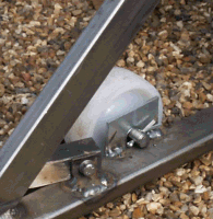
An order of nylon wheels arrived today from RS that I was going to use at the front of the robot to keep the flipper just running off the ground. I chose simple wheels instead of swiveling castors because I could save on weight as well as provide some straight line stability. The wheels were not that wide and wouldn't provide a lot of friction, so I would expect to be able to spin the hog on the spot without too much trouble The wheels were nice and cheap, but were just the wheels without any mounting bracket. After a bit of head scratching and digging around in the garage I found some plates and bolts that I could use to mount the wheels on. I also found a length of metal tube that I thought might be good to use as a plain sleeve bearing on the wheel axle. It was an interference fit with the wheel, so I heated it with a blow torch and then pushed the tube through the axle by clamping in the vice. When it had cooled down, it was fixed tightly in the wheel. |
 |
Friday 21st March 2003
|
I unbolted the tusks from Hassock Hog 1 and mounted them in the same place on HH2. I was still waiting for the regulator and buffer tank to be completed by Life Support Services, so in the absence of these, I continued with some of the pneumatic piping. |
 |
Saturday 22nd March 2003
I tested out the pneumatics as best I could today, given that I didn't have all the components like a high flow rate regulator, and valve controller. Instead I connected a few trailing wires to a couple of the relevant valves, and ran a long piece of pipe from my CO2 gas bottle to the buffer tank. By connecting a battery to the trailing wires I could fire the pneumatics while standing a safe distance away from the Hog. Initially the flipper shot a couple of go kart tyres a long way into the air, but its response in trying to self right was a little disappointing.
I had based the pneumatics on the robot M2, which solidly threw itself back onto its wheels, whereas the Hog certainly was not throwing itself anywhere. I did a bit of head scratching and then wondered if the high flow rate valves were "soft starting". These valves had to be operated by a 10 bar gas feed which came from the main 16 feed through a second regulator. I hadn't bothered to check the pressure on the downward side of this second regulator so thought that maybe it wasn't high enough to operate the high flow rate valves quickly enough.
To check it out I connected a pressure gauge to the downward side for this second regulator and noted that the pressure was about 5 bars. I adjusted it up to 10 bars and then tried the flipper again. This made a tremendous difference and not only did the flipper now shoot a couple of go-kart wheels as high at the roof of the house, but when trying to self right, it really did throw itself off the ground. You can see it in action on my video page, or by clicking here.
Saturday 29th March 2003
Now that I had gone as far as I could with the pneumatics because I was awaiting the delivery of my custom build high flow rate regulator, I turned my attentions to sighting the motor controller. I had initially hoped to put it somewhere at the front of the robot, as far away form the motors as I could. However, the routing of the pneumatic piping was occupying a lot of the space immediately above the batteries and would make it next to impossible for me to mount the gas bottle there as well. This left only the front of the robot in which to put the bottle, and therefore the motor controller could go nowhere else but right next to the batteries and motors. Not ideal, but I have little choice at the moment.
|
I had to change the layout of the controller box and MOSFET bricks in order for them to fit into the space I had spare. I made a couple of brackets up out of aluminium angle and some 6mm aluminium bars, and used these to mount the bricks immediately under the controller box. I also found enough room to mount the safety link at the top rear of the Hog, which meant the battery leads would be extremely short and tidy. The next thing was to try and complete the wiring between the bricks, the battery, the safety link, the safety contactor, and the motors. I tried to keep this as short and tidy as I could so as not to waste too much power in voltage drops along the way. |
 |